Description
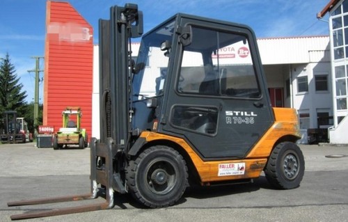
Original Still R70-35T, R70-40T, R70-45T LPG Fork Truck Service Repair Manual is a Complete Informational Book. This Service Manual has easy-to-read text sections with top quality diagrams and instructions. Trust Still R70-35T, R70-40T, R70-45T LPG Fork Truck Service Repair Manual will give you everything you need to do the job. Save time and money by doing it yourself, with the confidence only a Still R70-35T, R70-40T, R70-45T LPG Fork Truck Service Repair Manual can provide.
Service Repair Manual Covers:
Group 01 Chassis and counterweight
Group 02 Steering axle
Group 03
Technical service data
Gear drive
Spur gearing with differential
Fitting the gear drive
Gear drive/tubular shaft
Axle shaft
Wheel hub
Group 04
Technical service data
Wheels and tyres
Group 06
Technical service data
Mode of operation
Functional description
Steering column
Steering unit
Priority valve
Steering cylinder
Group 07
Technical service data
Design/mode of operation of the brake
Brake shoe replacement/Basic adjustment
Automatic adjuster
Adjusting the parking brake
Pedal adjustment
Turning worn brake drum
Group 08
Technical service data
Electrical installation
Electrical components
General
Insulation test
Instrument panel
Console
Lock switch
Travel sender (single-pedal)
Travel sender switch (single-pedal)
Two-pedal control
Horn
Brake sender
Parking brake switch
Brake fluid switch
Pressure transducer, hydraulic
Speed sensor
Tacho-alternator
Alternator
Starter
Emergency start switch
Cut-out valve
Coolant temperature switch/sender
Oil pressure/air cleaner/LPG pressure switch
Current sensor
Electric fan (Vengine)
Valve solenoid
Retarder
Batteries
Fuse base
Control fuses
Main current fuses
Starting relay
Relay tripping valve
Controller, (includes)
Travel control
Charge equaliser
Output stage for travel control
Output stage for electric fan
Controller renewal
Instrument panel renewal
Fault indication on the console (see steds/Info/error lists)
Circuit diagram (paper)
Group 09
Design of lighting installation
Variants
Status A: Controller, distributor board
Status B: Controller, relay box, distributor board
Status C: Controller, 2 x relay boxes
Relays
Fuses
Relay box
Distributor board
Parameterisation
Parameterisation of additional electrical installation via console
Combination of function blocks via console
Group 10
Technical service data
Hydraulic system
Functional description
of lift and tilt hydraulics
Control valve block
Operation
Design
Design/Installation information
Function diagram
Connection block
Plate/Retarder
Endplatte / Retarder
Way valve
Lift/Lower
Tilt/Additional hydraulics
Additional hydraulics
Control valve block
Cross-section reducer installation tilt/block seal
Shuttle valves
Sender- function/adjustment
Engine – pumps speed
Pressurising valve
Function
Checking/Disassembly
Hydraulic pump
Function/removal and fitting
Hydraulic tank
Design/Oil change/Air filter
Return flow filter
Function/Maintenance
Oil cooler
Hydraulic unions
Tilt cylinder and DKO unions
Pipe unions with soft seal
Speeds
Lift/lower/tilt
Hydraulic diagram
Wiring diagram
Legend
Group 11
Motor
Motor type
Diagram
Neutral zone
Position of motor terminals
Connection of brush and temperature monitoring unit
Checking and replacing carbon brushes
Removing the motor
Fitting the motor
Motor disassembly
Motor assembly
Generator
Generator type
Diagram
Neutral zone
Position of generator terminals
Checking and replacing carbon brushes
Removing the generator
Fitting the generator
Generator disassembly
Generator assembly
Independent air cooling
Description
Brush monitoring unit
Temperature monitoring
General information
Insulation resistance
Insulation resistance measurement
Turning the commutator
Commutator minimum diameter
Removing commutator mica
Group 13
Technical service data
Pressure regulator I and II
Function
Pressure regulator
Relief valve
Pressure gauge
Control valve block
Cross-section reducer installation
Pressure limitation additional hydraulics
(clamps with integrated side shift)
Group 15
Technical engine data
General engine information
V-belt Replacement and tensioning
Valve cover Fitting and removal
Rocker Fitting and removal
Valve Clearance adjustment
Cylinder head
General description
Cylinder head Fitting and removal
Alternator Fitting and removal
Thermostat
Coolant pump
Fitting and removal
Exhaust manifold
Coolant radiator
Control housing and control wheels
Electronic ignition system
– Description
– Advance angle sensor
– Ignition unit Removal and fitting
Troubleshooting
Group 20-Group 25
Group 20
Technical service data
Mast removal
Telescopic mast
Niho mast
Triple mast
Carriage stop/Chain adjustment
Support roller replacement
Lift cylinder
Lowering brake valve
Hose failure safety device
End position damping
Group 22
Fork carriage removal
Support roller replacement
Group 25
Tilt cylinder disassembly
Tilt cylinder assembly
Mast tilt
File Format: PDF
Compatible: All Versions of Windows & Mac
Language: English
Requirements: Adobe PDF Reader
Its important to buy the right repair manual for your Still R70-35T, R70-40T, R70-45T LPG Fork Truck. It is great to have, will save you a lot and know more about your Still R70-35T, R70-40T, R70-45T LPG Fork Truck, in the long run. All pages are printable.
Thanks for visiting!